EV/HEV向け放電抵抗器 ― 安全設計と選定のポイント Discharge resistors for EV/HEV – Safety design & key selection points
なぜ「放電抵抗器」が安全設計の要になるのか Why discharge resistors are key to safety design
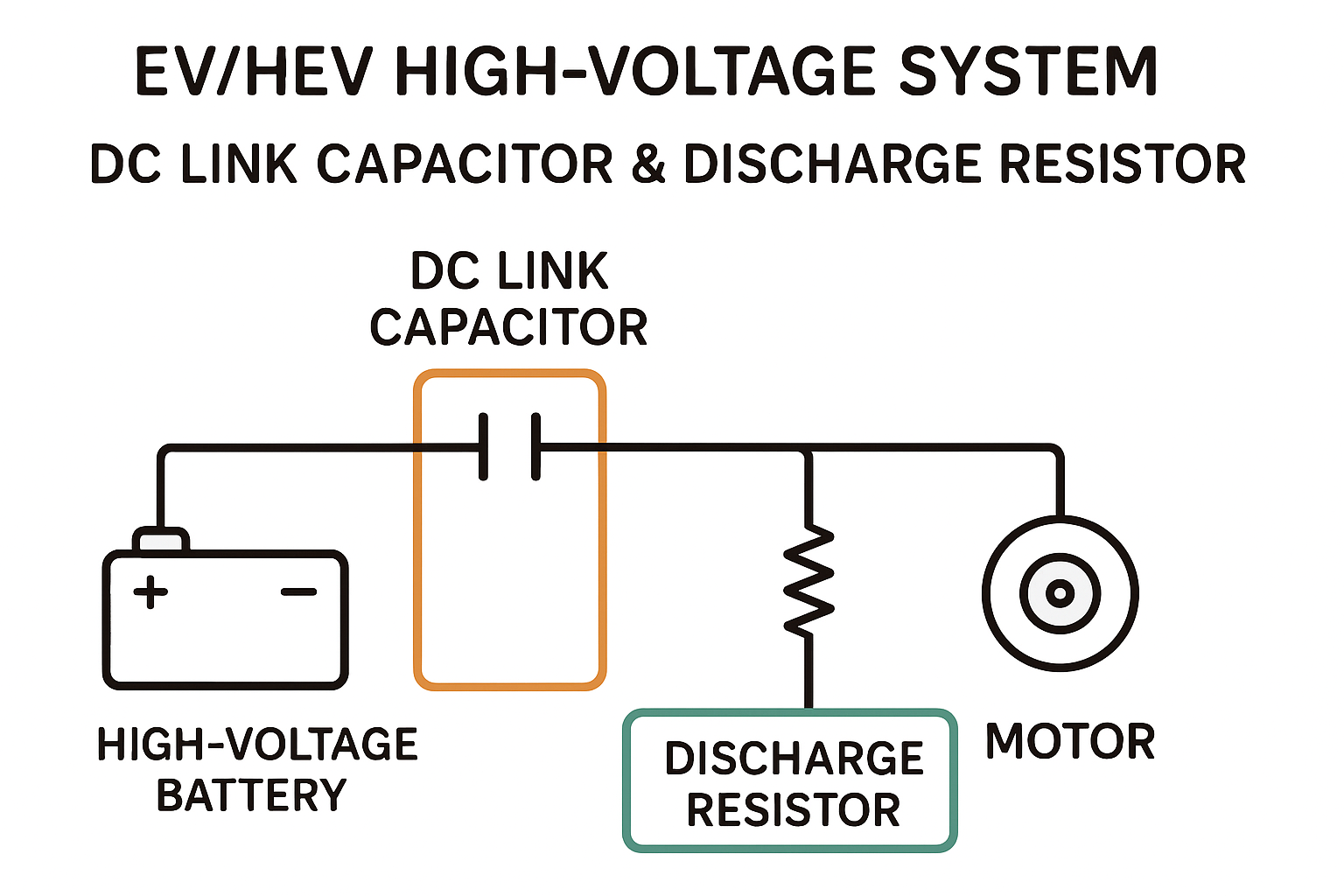
電動車両(EV / HEV)の高電圧システムでは、コンデンサに蓄えられたエネルギーを
どのように、どれくらいの時間で、安全に放電するか が重要なテーマです。
本コラムでは、EV/HEV向けの放電抵抗器について、設計時に押さえておきたい
「放電時間」「パルス耐久」「絶縁」「振動・温度サイクル」などのポイントを整理します。
In high-voltage systems of electric and hybrid vehicles (EV / HEV),
it is crucial to determine how, and within what time, the stored energy in capacitors is safely discharged.
In this column, we organize key design points for discharge resistors for EV/HEV,
including “discharge time,” “pulse endurance,” “insulation,” and “vibration / thermal cycling.”
1. 放電抵抗器の役割と「放電時間」の考え方 1. Role of discharge resistors and the concept of “discharge time”
放電抵抗器の役目はシンプルです。すなわち、 「コンデンサに蓄積されたエネルギーを、規定時間内に、安全に消費する」 ことです。 The role of a discharge resistor is simple: “to safely dissipate the energy stored in a capacitor within a specified time”.
車載システムでよく見られる設計条件の例を表形式で整理すると、以下のようになります。 Typical design conditions often seen in automotive systems can be summarized as follows:
- 初期電圧:400〜800V クラス Initial voltage: 400–800 V class
- 許容残留電圧:60V以下(規格・社内基準など) Allowable residual voltage: 60 V or less (based on standards and in-house criteria)
- 放電時間:1〜5秒程度(ECUや安全回路の仕様に依存) Discharge time: about 1–5 seconds (depending on ECU and safety-circuit specifications)
- 設置環境:高温・振動・湿度など、厳しい車載環境 Installation environment: harsh automotive conditions such as high temperature, vibration, and humidity
一般に、放電時間を短く設定するほど安全性は高まりますが、 抵抗値が小さくなり、放電時の電力(瞬間負荷)が大きくなる ため、 放電抵抗器にはより高い性能・信頼性が求められます。 In general, the shorter the discharge time, the higher the safety margin. However, this also means a smaller resistance value and higher power (instantaneous load) at discharge, which requires higher performance and reliability from the discharge resistor.
2. 選定ポイント①:パルス耐久と過渡熱 2. Key point (1): Pulse endurance and transient thermal behavior
放電動作は、連続負荷ではなく 短時間・大電力のパルス負荷 です。 重要なのは、抵抗器が瞬間的な熱を吸収し、破壊や性能劣化を起こさないことです。 Discharge operation is not a continuous load, but a short-duration, high-power pulse load. What matters is that the resistor can absorb this transient heat without damage or performance degradation.
中村電機工業では、抵抗体・放熱板・封止構造などを組み合わせ、 過渡熱ストレスに強い放電用抵抗器 を設計・製造しています。 At Nakamura Electric Industry, we combine resistor elements, heat-spreading plates and sealing structures to design and manufacture discharge resistors with high tolerance to transient thermal stress.
- 許容エネルギー(Joule Energy, J) Allowable energy (Joule energy, J)
- 実装状態での放熱経路(ヒートシンク/筐体との熱結合) Heat dissipation path in actual mounting (thermal coupling to heat sink / enclosure)
- 繰り返し放電時の温度上昇と疲労 Temperature rise and fatigue under repeated discharge
- 抵抗値変動(ドリフト)の許容範囲 Acceptable range of resistance drift
- クラック・剥離の検査方法と判定基準 Inspection methods and criteria for cracks and delamination
実務の現場では、机上での電力計算は成立していても、 実装状態の熱集中を十分に評価できていない ために、 耐久試験で不具合が見つかるケースも少なくありません。 In practice, even if power calculations on paper are correct, insufficient evaluation of thermal concentration in the actual mounted state can lead to failures discovered in endurance testing.
3. 選定ポイント②:高電圧絶縁と安全クリアランス 3. Key point (2): High-voltage insulation and safety clearance
高電圧システムにおいては、抵抗値だけでなく 絶縁性能とクリアランス設計 が非常に重要です。 乾燥時と湿潤時で必要な絶縁距離が異なることに加え、 材料の吸湿・ガス化・熱劣化なども長期信頼性に影響します。 In high-voltage systems, not only the resistance value but insulation performance and clearance design are crucial. Required insulation distances differ between dry and humid conditions, and material absorption of moisture, gas generation and thermal aging also affect long-term reliability.
当社では、特殊絶縁材・表面処理・封止構造などを組み合わせることで、 長期にわたり安定した絶縁性能を確保 する設計を行っています。 We combine special insulating materials, surface treatments and sealing structures to achieve designs that provide stable insulation performance over the long term.
4. 選定ポイント③:振動・温度サイクルなどの環境ストレス 4. Key point (3): Environmental stress such as vibration and temperature cycling
車載環境では、以下のようなストレスが同時にかかることが一般的です。 In automotive environments, the following stresses typically act simultaneously:
- -40℃〜+125℃クラスの温度サイクル Temperature cycling in the −40 °C to +125 °C range
- ランダム振動・衝撃 Random vibration and mechanical shock
- 湿度・塩害・結露 など Humidity, salt damage, condensation, etc.
抵抗器本体が壊れていなくても、 端子や固定部に機械的ストレスが集中し亀裂が発生する 例もあります。 放電抵抗器の評価では、電気特性だけでなく、 実際の取り付け方法や筐体設計も含めた総合的な検討が重要です。 Even if the resistor body itself is intact, there are cases where mechanical stress concentrates on terminals or mounting parts, causing cracks. Evaluation of discharge resistors must therefore consider not only electrical characteristics but also mounting methods and enclosure design as part of a comprehensive review.
5. 実際のトラブル事例(一般化・匿名) 5. Actual trouble cases (generalized / anonymized)
→ 実装状態での熱集中が想定より大きく、 放熱設計を見直すことで改善しました。 · Although the specification for discharge time was satisfied, endurance testing revealed a gradual increase in resistance value, leading to failures in surrounding components.
→ Thermal concentration in the mounted state was higher than expected, and the issue was resolved by reviewing and improving the thermal design.
→ 熱応力と機械応力の複合ストレスに対する評価が不足しており、 固定構造と端子形状の変更により改善しました。 · Although power tests were passed, vibration testing in a vehicle-mounted environment revealed cracks at the boundary between the terminal and its fixing section.
→ Evaluation of combined thermal and mechanical stress was insufficient; the problem was solved by changing the fixing structure and terminal shape.
6. まとめ ― 「抵抗値」だけでは語れない、放電抵抗器の最適設計 6. Summary – Optimal design of discharge resistors cannot be judged by resistance value alone
放電抵抗器の選定では、カタログ上の抵抗値・定格電力だけでは不十分な場面が多くあります。 実際の設計では、次のような観点を総合的に評価することが、信頼性向上の鍵となります。 When selecting discharge resistors, catalog resistance values and power ratings alone are often insufficient. In actual design, comprehensively evaluating the following aspects is key to improving reliability:
- 放電条件に対するエネルギー吸収能力(パルス耐量)の確認 Verifying energy absorption capability (pulse endurance) under discharge conditions
- 実装状態を含めた熱設計・放熱経路の検討 Reviewing thermal design and heat dissipation paths including the mounted state
- 長期使用を見据えた絶縁性能とクリアランス設計 Designing insulation performance and clearance for long-term use
- 温度サイクル・振動・湿度など、環境ストレスの複合評価 Evaluating combined environmental stresses such as temperature cycling, vibration and humidity
- 抵抗値変動や機械的信頼性も含めたトータル設計 Total design including resistance drift and mechanical reliability
「抵抗値」だけで部品を選ぶのではなく、使用環境や安全要求を踏まえた総合的な設計。 それが、EV/HEV時代の放電抵抗器に求められるアプローチです。 Instead of choosing components based only on “resistance value,” a comprehensive design that takes into account the actual operating environment and safety requirements is essential. This is the approach required for discharge resistors in the EV/HEV era.
お気軽にお問い合わせください。 From supporting discharge time and energy calculations to reviewing existing resistors and discussing evaluation tests,
please feel free to contact us.